Securing The Future Bit By Bit

Monday, August 26, 2019

Privacy Policy


Privacy Policy
Effective date: August 27, 2019

ElectrocoreDIY ("us", "we", or "our") operates the https://electrocorediy.blogspot.com/ website (the "Service").

This page informs you of our policies regarding the collection, use, and disclosure of personal data when you use our Service and the choices you have associated with that data. Our Privacy Policy for ElectrocoreDIY is created with the help of the Free Privacy Policy Generator.

We use your data to provide and improve the Service. By using the Service, you agree to the collection and use of information in accordance with this policy. Unless otherwise defined in this Privacy Policy, terms used in this Privacy Policy have the same meanings as in our Terms and Conditions, accessible from https://electrocorediy.blogspot.com/

Information Collection And Use
We collect several different types of information for various purposes to provide and improve our Service to you.

Types of Data Collected
Personal Data
While using our Service, we may ask you to provide us with certain personally identifiable information that can be used to contact or identify you ("Personal Data"). Personally, identifiable information may include, but is not limited to:

Cookies and Usage Data
Usage Data
We may also collect information about how the Service is accessed and used ("Usage Data"). This Usage Data may include information such as your computer's Internet Protocol address (e.g. IP address), browser type, browser version, the pages of our Service that you visit, the time and date of your visit, the time spent on those pages, unique device identifiers and other diagnostic data.

Tracking & Cookies Data
We use cookies and similar tracking technologies to track the activity on our Service and hold certain information.

Cookies are files with a small amount of data which may include an anonymous unique identifier. Cookies are sent to your browser from a website and stored on your device. Tracking technologies also used are beacons, tags, and scripts to collect and track information and to improve and analyze our Service.

You can instruct your browser to refuse all cookies or to indicate when a cookie is being sent. However, if you do not accept cookies, you may not be able to use some portions of our Service.

Examples of Cookies we use:

Session Cookies. We use Session Cookies to operate our Service.
Preference Cookies. We use Preference Cookies to remember your preferences and various settings.
Security Cookies. We use Security Cookies for security purposes.
Use of Data
ElectrocoreDIY uses the collected data for various purposes:

To provide and maintain the Service
To notify you about changes to our Service
To allow you to participate in interactive features of our Service when you choose to do so
To provide customer care and support
To provide analysis or valuable information so that we can improve the Service
To monitor the usage of the Service
To detect, prevent and address technical issues
Transfer Of Data
Your information, including Personal Data, may be transferred to — and maintained on — computers located outside of your state, province, country or other governmental jurisdiction where the data protection laws may differ than those from your jurisdiction.

If you are located outside India and choose to provide information to us, please note that we transfer the data, including Personal Data, to India and process it there.

Your consent to this Privacy Policy followed by your submission of such information represents your agreement to that transfer.

ElectrocoreDIY will take all steps reasonably necessary to ensure that your data is treated securely and in accordance with this Privacy Policy and no transfer of your Personal Data will take place to an organization or a country unless there are adequate controls in place including the security of your data and other personal information.

Disclosure Of Data
Legal Requirements
ElectrocoreDIY may disclose your Personal Data in the good faith belief that such action is necessary to:

To comply with a legal obligation
To protect and defend the rights or property of ElectrocoreDIY
To prevent or investigate possible wrongdoing in connection with the Service
To protect the personal safety of users of the Service or the public
To protect against legal liability
Security Of Data
The security of your data is important to us, but remember that no method of transmission over the Internet, or method of electronic storage is 100% secure. While we strive to use commercially acceptable means to protect your Personal Data, we cannot guarantee its absolute security.

Service Providers
We may employ third party companies and individuals to facilitate our Service ("Service Providers"), to provide the Service on our behalf, to perform Service-related services or to assist us in analyzing how our Service is used.

These third parties have access to your Personal Data only to perform these tasks on our behalf and are obligated not to disclose or use it for any other purpose.

Links To Other Sites
Our Service may contain links to other sites that are not operated by us. If you click on a third party link, you will be directed to that third party's site. We strongly advise you to review the Privacy Policy of every site you visit.

We have no control over and assume no responsibility for the content, privacy policies or practices of any third party sites or services.

Children's Privacy
Our Service does not address anyone under the age of 18 ("Children").

We do not knowingly collect personally identifiable information from anyone under the age of 18. If you are a parent or guardian and you are aware that your Children has provided us with Personal Data, please contact us. If we become aware that we have collected Personal Data from children without verification of parental consent, we take steps to remove that information from our servers.

Changes To This Privacy Policy
We may update our Privacy Policy from time to time. We will notify you of any changes by posting the new Privacy Policy on this page.

We will let you know via email and/or a prominent notice on our Service, prior to the change becoming effective and update the "effective date" at the top of this Privacy Policy.

You are advised to review this Privacy Policy periodically for any changes. Changes to this Privacy Policy are effective when they are posted on this page.

Contact Us
If you have any questions about this Privacy Policy, please contact us:

By email: electrocore210@gmail.com
Share:

Tuesday, July 23, 2019

Servo motor interfacing with Raspberry pi 3

In this blog,I will explain you how to interface servo motor with Raspberry pi 3.


This project uses Python scripts run on a Raspberry Pi microcontroller to send GPIO PWM outputs to a servo motor to set its angle. If all that sounds confusing, don't worry, I'm about to explain it.

Components Required

1. Raspberry pi 3
2. Servo motor
3. Jumper wires

Circuit Diagram


Connections

Raspberry pi-----------------------------Servo motor
  VCC(pin2)-------------------------------Servo red wire
  GND(pin39)-----------------------------Servo black wire
  GPIO4(pin7)----------------------------Servo orange wire

A servo motor is a type of DC motor that, upon receiving a signal of a certain frequency, can rotate itself to any angle from 0-180 degrees. Its 90 degree position is generally referred to as 'neutral' position, because it can rotate equally in either direction from that point.

Procedure

Step1- Make connection as shown in above figure.
Step2- connect red wire of servo to pin2 of raspberry pi and black wire of servo to                    pin39 of raspberry pi and orange wire of servo to pin 7 of raspberry pi.
Step3- Download the code from given link.
Step4- Open the downloaded file in python software.
Step5- If you want change the GPIO pin just edit it with your own GPIO pin.
Step6- Run the program anf you will see servo start moving.

 Download the code from here

Media Gallary


Share:

Monday, July 22, 2019

Raspberry pi with DHT11 sensor step by step full tutorial.

In this blog, I will explain you how to connect raspberry pi with dht11 sensor and measure the temperature and humidity readings. 

Components Required

1. Raspberry Pi 3
2. DHT11 sesnor
3. Breadboard
4. Jumper wires

Circuit Diagram

Step1- Make a connection as shown in above figure.
Step2- Connect DHT VCC pin to pin1 of raspberry pi and GND pin of DHT to pin39 of raspberry pi              and connect data pin of DHT to pin7 of raspberry pi.
Step3- Download the DHT11 code from given link.
Step4- Folder contain two python files one is code and another act as library. Both files must be in                  same folder.

Download Code


Media Gallary

Share:

Blink Led using Raspberry pi 3 with Python script.

In this blog, I will explain how to blink a led using raspberry pi 3 with python code.


Components Required
1. Raspberry pi 3
2. Led
3. jumper wires
4. Breadboard
5. 220 ohm Resistor

Circuit Diagram

Step1- Make connection as shown in above figure.
Step2- Connect led +ve pin to 7 pin of raspberry pi and -ve pin of led to 39 pin of raspberry pi.
Step3- Resistor must be connected otherwise led will fused.
Step4- Download the code and upload the raspberry pi.
via element14.com

Program Code

import RPi.GPIO as GPIO
import time
GPIO.setmode(GPIO.BOARD)
GPIO.setup(7,GPIO.OUT)

i = 1
while(i<=5):
    GPIO.output(7,True)
    time.sleep(1)
    GPIO.output(7,False)
    time.sleep(1)
    i = i + 1
GPIO.cleanup()


Download code file from here

Media Gallary


Share:

Thursday, July 18, 2019

How to make a quadcopter using esp8266 and controlled it by your smart phone.

In this blog, I will explained you how to build esp8266 based quadcopter using Arduino Uno and controlled it by smart phone.


Components Required

1. Arduino uno
2. ESP-01/ESP-12
3. MPU6050
4. ESC(Electronic Speed Controller)
5. Brushless DC motors
6. Breadboard
7. Jumper Wires
8. Quadcopter Frame
9. FTDI or TTL

Procedure to make WIFI Quadcopter

Step1-make a connection of esp01 as given.


Step2- Open the wifippm code
         -->If you are using esp8266(esp-12) set GPIO5 pin as PPM output pin and GPIO4                pin as debug pin.
         -->If you are using esp8266(esp-01) set GPIO2 pin as PPM output pin and GPIO3                pin as debug pin.

Step3- upload the wifippm code to esp01 with the help ttl or ftdi.


Step4- After upload the code remove the Rx Tx GPIO0 and CH_pd pins.If a hotspot is              created named wifippm then everythings is alright.

            If hotspot is not created then connect Ch_pd pin to 3.3v and reset the                            esp01(means off and again on).


Step5- Now place all the components on the frame and make a connection as shown              in figure

Circuit Diagram


 Step6- open multiwii.ino firmware go to config.h and uncomment the following                   lines.
             The type of multicopter----------> #define QUADX 
             Combined IMU Boards-------------> #define GY_521 
             PPM Sum Reciver ------------------> #defineSERIAL_SUM_PPM(PITCH,ROLL,THROTTLE,YAW)      

Step7- upload the code in arduino uno board.

Step8- open the multiwii gui select the board and click the start button. Move your                   quadcopter and you can seen the reading of gyroscope and acclerometer.                 
Step9- connect your phone with wifipmm hotspot and open any browser and type                    192.168.4.1


Step10- move the joystic in browser and you can see the changes in multiwii gui.

My Github link-https://github.com/amanjaiswal210


Download wifi_ppm code here
Download Multiwii firmwar from here

Media Gallary


Share:

Thursday, July 11, 2019

How to make DIY quadcopter using Arduino Uno.

In this blog, I will explained you how to build your own quadcopter using Arduino Uno.


Components Required

1. Arduino Uno
2. Quadcopter Frame typeX
3. Flysky Receiver
4. 6 Channel Transmitter
5. 4 ESC 30A
6. MPU6050
7. 4 Brushless DC Motor

About Quadcopter

Quadcopters generally use two pairs of identical fixed pitched propellers; two clockwise (CW) and two counterclockwise (CCW). These use independent variation of the speed of each rotor to achieve control. By changing the speed of each rotor it is possible to specifically generate a desired total thrust.Each rotor produces a thrust and a torque about its center of rotation and these forces are used to fly and move quadcopter. Two rotors mounted on opposite arms of quadcopter are set into clockwise and another two anticlockwise direction of motion. These position of motors and their direction of rotation cancels all the torque generated given the speed of the motors are same.

Circuit Diagram

Design by Aman Jaiswal


Why Arduino as a flight controller ?

There are lots of flight controller available in Market like
1.Naze32 Flight Controller
2.OpenPilot CC3D Flight Controller
3.EagleTree Vector Flight Controller
4.Hobbyking KK2.1 Flight Controller
5.ArduPilot Mega APM 2.5Flight Controller
But i chosed Arduino Uno because it cheap and easy availabe in market.
Arduino uno work on Atmega328p microcontroller which is 8 bit microcontroller have enough processing speed and Clock Speed 16 MHz, Can provide 8-bit PWM output with the analogWrite() function.

About Transmitter and Receiver

For my quadcopter I used FlySky CT6B 2.4Ghz 6CH Transmitter with FS-R6B Receiver is the popular 6 Channel Radio CT6B manufactured by FlySky.CT6B FLYSKY 2.4GHZ 6CH TRANSMITTER radio is a value for money, entry level 6 channel transmitter, ideal for quadcopters and multicopters that require the 6ch operation.CT6B FLYSKY 2.4GHZ 6CH TRANSMITTER is an entry-level 2.4 GHz radio system offering the reliability of 2.4 GHz signal technology and a receiver with 6 channels. It can be powered by 8 x AA Size Batteries or a 12V Power Supply. It comes with a trainer port to help beginners learn flying.It can be configured by connecting it to the computer. Use the T6config software to configure your radio on a computer.


About Electronic Speed Controller

I used 30A BLDC ESC ELECTRONIC SPEED CONTROLLER can drive motors which consume up to 30A current. It works on 2S-3S LiPo batteries. It has an onboard BEC which provides regulated 5V(2A max draw) to power the flight controller and other onboard modules. It can be used to control our brushless motors with a 2S-3S LiPo (make sure motor doesn’t draw more than 30A).30A BLDC ESC Electronic Speed Controller is specifically made for quadcopters and multi-rotors and provides faster and better motor speed control giving better flight performance compared to other available ESCs.


How to configure your Quadcopter
Step1 Download and compile setup code. 
Step2 Download and compile ESC calibration code.
Step3 Finally download and compile Flight code.

How to control your quadcopter

Controlling a quadcopter is alway risky make sure all four propellers are tightly screwed .Don't try this at home.For Arming the quadcopter put throttle down and put yaw left now slowly move the throttlr up. For Disarming the quadcopter put the throttle down and put the yaw right.
via research gate
Credit 

Media Gallary


Share:

Saturday, July 6, 2019

How to make mini and cheap quadcoptor using eachine flight controller.

In this blog,I will explain you how to make cheap and mini quadcopter using eachine flight controller.


Components Required

1. Four Coreless Dc motors(8520)
2. Quadcopter FrameQ100 TypeX
3. Eachine flight controller
4. 2.4GHz Transmitter.
5. Two 65 mm Propellers(CW)
6. Two 65 mm propellers(CCW)

Why Q100  Frame?

The Q100 is a mini-size smallest frame among the quadcopter frame class.This is ready-2-fly quadcopter frame requires only basic installation. You can enjoy the versatility of the Q100 racing drone by practicing your flying, racing, or aerial acrobatic drone skills either indoors when it’s raining, or outdoors when it’s sunny.The arms of the frame are attached permanently to the frame and can’t be removed. The upper colored cap at the front of the frame can be attached and detached while assembling.

Why Eachine h8 Flight Controller?

Basically It is receiver board Compatible with: JJRC H8 Mini QuadcopterItem dimension: 4.3 * 4.2 * 0.2cm .Its weight is only 3g. In this board we can connect four coreless DC motors. This board is highly stable as compared to other boards at this price. It works on 2.4ghz radio frequency. It is compatible with any transmitter which work on 2.4GHz.

Why 8520 coreless motor?

This 8520 Magnetic Micro Coreless Motor is very compact and lightweight DC motor nicely crafted for perfectly matching with your small 100mm like multirotor frames.These lightweight brushed DC coreless motors are the best choice for your small drone, offering you an excellent affordable price when compared with costly BLDC motors.They are rated at 39000 RPM which is more than needed to lift and push your drone to the target. These are less noisy with low resistance. The only drawback of using coreless is the amount of torque they provide, as they are High Speed and Low Torque motors.

Why 2.4GHz Transmitter? 

2.4GHz system is an entry level transmitter offering the reliability of 2.4GHz signal technology and a twin receiver antenna and with 6 channels.This transmitter requires 8 AA batteries.Easy to use control for basic models.We can use this for all sorts of projects including (but not limited to) tanks, airplanes, helicopters, scale models of the Weinermobile.This radio has very lightweight and handy design with two retract switches and proportional flap dials in easy reach for channels 5 and 6.
Credits

Media Gallary


Share:

Friday, July 5, 2019

Smart Water Pump using GSM SIM900A module

In this blog, I will explain you how to make a smart water pump which can be controlled by a cellular  phone.

Components Required

1. Arduino Uno
2. SIM 900A module
3. 9v Relay
4. Water Pump
5. 16*2 Lcd Display
6. I2c Display module
7. 9v Battery
8. Jumper wires

Circuit Diagram
Design in Fritzing 


In this circuit,I am using SIM900A module but you can also use SIM800L module.I am using SIM900A module due to following features.

  • Best suited for GSM based Microcontroller Projects (better than SIM300 and other GSM Modems)
  • Option for connecting MIC and SPEAKER directly to GSM MODEM for calls (LINE IN also available)
  • Compatible with ARDUINO, RASPBERRY PI, ARM, AVR, PIC, 8051, etc. - Can also be directly connected to computer via Serial Port (Use GSM Tester or write your own Software)
  • Supports communication through RS232 with DB9 Connector, TTL Pins & I2C Pins
  • CALL SMS GPRS facility - MIC input, LINE input & SPEAKER output pins.


Arduino Code


#include <LiquidCrystal_I2C.h>
#include <SoftwareSerial.h>
#include <EEPROM.h>
SoftwareSerial gsm(2, 3); // RX, TX
LiquidCrystal_I2C lcd(0x27, 16, 2);
// ----------- ----------- //
int address = 0; // <<<<<<< Change address = 10 in case of EEPROM failure.
int wr_call_add = 1; // <<<<<<<< Change wr_call_add = 11 in case of EEPROM failure.
int f_address = 2; // <<<<<<<<< Chnage f_address = 12 in case of EEPROM failure.
int eeprom_dead = 3; // <<<<<<<<<< Change eeprom_dead = 13 inc case of EEPROM failure.
// ----------- ----------- //
int wr_call_val = 0;
int f_value = 70;
int value = 0;
int ring = 0;
int i = 0;
int var = 0;
int eeprom_tst = 0;
int eeprom_tst_ack = 0;
int tst_var = 100;
int wr_call_tst = 100;
int eeprom_dead_val = 0;
String number = "";
String string = "";
const int output = 8;
boolean wait = true;
boolean at_flag = 1;
boolean net_flag = 1;
// ================ ============== //
char str[] = "91xxxxxxxxxx";
// ================= ============= //
// Replace xxxxxx your phone number starting with "91" which is India country code.
// Replce "91" with your own country code, if outside India.
void setup()
{
Serial.begin(9600);
lcd.init();
lcd.backlight();
gsm.begin(9600);
pinMode(output, OUTPUT);
if (EEPROM.read(f_address) != f_value)
{
EEPROM.write(f_address, f_value);
EEPROM.write(address, value);
EEPROM.write(wr_call_add, wr_call_val);
eeprom_dead_val = 0;
EEPROM.write(eeprom_dead, eeprom_dead_val);
}
if (EEPROM.read(eeprom_dead) == 1)
{
while (true)
{
lcd.clear();
lcd.setCursor(0, 0);
lcd.print("EEPROM Error.");
lcd.setCursor(0, 1);
lcd.print("System Disabled.");
delay(1500);
lcd.clear();
lcd.setCursor(0, 0);
lcd.print("Reload the code");
lcd.setCursor(0, 1);
lcd.print("with new address");
delay(1500);
}
}
if (EEPROM.read(address) == 0)
{
digitalWrite(output, LOW);
gsm_init();
lcd.clear();
if (EEPROM.read(wr_call_add) == 0)
{
lcd.setCursor(0, 0);
lcd.print("Sending SMS");
lcd.setCursor(0, 1);
lcd.print("Acknowledgement.");
delay(1000);
gsm.println("AT+CMGF=1");
delay(500);
gsm.print("AT+CMGS=");
gsm.print("\"");
gsm.print(str);
gsm.println("\"");
delay(1000);
gsm.println("Motor is OFF / System is Ready.");
delay(100);
gsm.println((char)26);
}
if (EEPROM.read(wr_call_add) == 1)
{
wr_call_val = 0;
EEPROM.write(wr_call_add, wr_call_val);
}
}
if (EEPROM.read(address) == 1)
{
eeprom_test();
output_begin();
}
}
void(* resetFunc) (void) = 0;
void loop()
{
serialEvent();
if (ring == 1)
{
number = "";
var = string.indexOf("+CLIP: \"");
if (var > 0)
{
number += string.substring(var + 8, var + 13 + 7);
}
if (number[0] == str[0] && number[1] == str[1] && number[2] == str[2] && number[3] == str[3]
&& number[4] == str[4] && number[5] == str[5] && number[6] == str[6] && number[7] == str[7]
&& number[8] == str[8] && number[9] == str[9] && number[10] == str[10] && number[11] == str[11])
{
gsm.println("ATH");
lcd.clear();
lcd.setCursor(0, 0);
lcd.print("Incomming call");
lcd.setCursor(0, 1);
lcd.print("Number Verified.");
delay(2000);
if (EEPROM.read(address) == 0)
{
EEPROM.write(address, 1);
}
else if (EEPROM.read(address) == 1)
{
EEPROM.write(address, 0);
}
resetFunc();
}
if (!(number[0] == str[0] && number[1] == str[1] && number[2] == str[2] && number[3] == str[3]
&& number[4] == str[4] && number[5] == str[5] && number[6] == str[6] && number[7] == str[7]
&& number[8] == str[8] && number[9] == str[9] && number[10] == str[10] && number[11] == str[11]))
{
gsm.println("ATH");
lcd.clear();
lcd.setCursor(0, 0);
lcd.print("Unknown number");
lcd.setCursor(0, 1);
lcd.print("Call Rejected.");
wr_call_val = 1;
EEPROM.write(wr_call_add, wr_call_val);
delay(2000);
resetFunc();
}
}
if (EEPROM.read(address) == 0)
{
serialEvent();
lcd.clear();
lcd.setCursor(0, 0);
lcd.print("System Standby");
lcd.setCursor(0, 1);
lcd.print("Status: OFF");
delay(1000);
}
else if (EEPROM.read(address) == 1)
{
lcd.setCursor(0, 0);
lcd.print("STATUS: ON");
lcd.setCursor(0, 1);
lcd.print("----------------");
}
}
void gsm_init()
{
lcd.print("System booting....");
lcd.setCursor(0, 1);
lcd.print("initiating......");
delay(1500);
lcd.clear();
lcd.setCursor(0, 0);
lcd.print("Checking Module");
lcd.setCursor(0, 1);
lcd.print("Connectivity....");
while (at_flag)
{
gsm.println("AT");
while (gsm.available() > 0)
{
if (gsm.find("OK"))
at_flag = 0;
}
delay(1000);
}
lcd.clear();
lcd.setCursor(0, 0);
lcd.print("Module");
lcd.setCursor(0, 1);
lcd.print("Connection: OK");
delay(1500);
eeprom_test();
lcd.clear();
lcd.setCursor(0, 0);
lcd.print("System is Ready");
lcd.setCursor(0, 1);
lcd.print("----------------");
delay(1500);
}
void serialEvent()
{
while (gsm.available())
{
char read_char = gsm.read();
string += read_char;
i++;

if (string[i - 4] == 'R' && string[i - 3] == 'I' && string[i - 2] == 'N' && string[i - 1] == 'G' )
{
ring = 1;
}
}
}
void output_begin()
{
digitalWrite(output, HIGH);
if (EEPROM.read(wr_call_add) == 0)
{
lcd.clear();
lcd.setCursor(0, 0);
lcd.print("Sending SMS");
lcd.setCursor(0, 1);
lcd.print("Acknowledgement.");
delay(1000);
gsm.println("AT+CMGF=1");
delay(500);
gsm.print("AT+CMGS=");
gsm.print("\"");
gsm.print(str);
gsm.println("\"");
delay(1000);
gsm.println("Motor is ON.");
delay(100);
gsm.println((char)26);
}
if (EEPROM.read(wr_call_add) == 1)
{
wr_call_val = 0;
EEPROM.write(wr_call_add, wr_call_val);
}
lcd.clear();
}
void eeprom_test()
{
lcd.clear();
lcd.setCursor(0, 0);
lcd.print("Testing EEPROM");
lcd.setCursor(0, 1);
lcd.print("Memory.");
delay(1500);
eeprom_tst = EEPROM.read(address);
eeprom_tst_ack = EEPROM.read(wr_call_add);
EEPROM.write(address, tst_var);
EEPROM.write(wr_call_add, wr_call_tst);
if (EEPROM.read(address) == tst_var && EEPROM.read(wr_call_add) == wr_call_tst)
{
EEPROM.write(address, eeprom_tst);
EEPROM.write(wr_call_add, eeprom_tst_ack);
if (EEPROM.read(address) != eeprom_tst || EEPROM.read(wr_call_add) != eeprom_tst_ack)
{
digitalWrite(output, LOW);
eeprom_dead_val = 1;
EEPROM.write(eeprom_dead, eeprom_dead_val);
lcd.clear();
lcd.setCursor(0, 0);
lcd.print("EEPROM Test is");
lcd.setCursor(0, 1);
lcd.print("Unsuccessful.");
delay(1500);
eeprom_sms();
}
else if (EEPROM.read(address) == eeprom_tst && EEPROM.read(wr_call_add) == eeprom_tst_ack)
{
lcd.clear();
lcd.setCursor(0, 0);
lcd.print("EEPROM Test is");
lcd.setCursor(0, 1);
lcd.print("Successful.");
delay(1500);
}
}
else if (EEPROM.read(address) != tst_var || EEPROM.read(wr_call_add) != wr_call_tst)
{
digitalWrite(output, LOW);
eeprom_dead_val = 1;
EEPROM.write(eeprom_dead, eeprom_dead_val);
lcd.clear();
lcd.setCursor(0, 0);
lcd.print("EEPROM Test is");
lcd.setCursor(0, 1);
lcd.print("Unsuccessful.");
delay(1500);
eeprom_sms();
}
}
void eeprom_sms()
{
lcd.clear();
lcd.setCursor(0, 0);
lcd.print("Sending SMS");
lcd.setCursor(0, 1);
lcd.print("Acknowledgement");
delay(1000);
gsm.println("AT+CMGF=1");
delay(500);
gsm.print("AT+CMGS=");
gsm.print("\"");
gsm.print(str);
gsm.println("\"");
delay(1000);
gsm.println("EEPROM error. System disabled. Please reload the code with new address.");
delay(100);
gsm.println((char)26);
while (true)
{
lcd.clear();
lcd.setCursor(0, 0);
lcd.print("EEPROM Error.");
lcd.setCursor(0, 1);
lcd.print("System Disabled.");
delay(1500);
lcd.clear();
lcd.setCursor(0, 0);
lcd.print("Reload the code");
lcd.setCursor(0, 1);
lcd.print("with new address");
delay(1500);
}
}


Media Gallary


References
Share:

Thursday, July 4, 2019

How to make a weather monitoring system using Google Firebase.

In this blog, I will explain you how to monitor weather and send the data to google firebase.

Components Required

1. Nodemcu(ESP8266)
2. DHT11/22 Sensor
3. Breadboard
4. Google Firebase Account
5. Jumper Wires

Circuit Diagram:

Connection 
DHT11              Nodemcu
 Gnd---------------Gnd
  Vcc---------------Vcc
  Data--------------D4

What is DHT11 Sensor?

DHT11 Temperature & Humidity Sensor features a temperature & humidity sensor complex with a calibrated digital signal output. By using the exclusive digital-signal-acquisition technique and temperature & humidity sensing technology, it ensures high reliability and excellent long-term stability. This sensor includes a resistive-type humidity measurement component and an NTC temperature measurement component, and connects to a highperformance 8-bit microcontroller, offering excellent quality, fast response, anti-interference ability and cost-effectiveness.


Google Firebase Setup
Firebase provides a realtime database and backend as a service. The service provides application developers an API that allows application data to be synchronized across clients and stored on Firebase's cloud. The company provides client libraries that enable integration with AndroidiOSJavaScriptJavaObjective-CSwift and Node.js applications. The database is also accessible through a REST API and bindings for several JavaScript frameworks such as AngularJSReactEmber.js and Backbone.js. The REST API uses the Server-Sent Events protocol, which is an API for creating HTTP connections for receiving push notifications from a server. Developers using the realtime database can secure their data by using the company's server-side-enforced security rules.

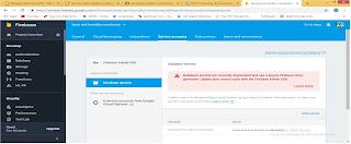
Step1 Make a account in google firebase and login .
Step2 Add a project with name.
Step3 Go to project overview then users and premissions.
Step4 Go to data base secret and then copy api key.
Step5 Go to database and change cloud firestore to realtime database.


Arduino Code
#include <ESP8266WiFi.h> // esp8266 library
#include <FirebaseArduino.h> // firebase library
#include <DHT.h> // dht11 temperature and humidity sensor library
#define FIREBASE_HOST "temp-and-humidity-monitoring.firebaseio.com" // the project name address from firebase id
#define FIREBASE_AUTH "ufKOoaJrqDbeK5rajoiheO7YcpKwFZSUrpm5jFRq" // the secret key generated from firebase
#define WIFI_SSID "Tenda_7F50C8" // input your home or public wifi name
#define WIFI_PASSWORD "Vansh024@" //password of wifi ssid
#define DHTPIN D4 // what digital pin we're connected to
#define DHTTYPE DHT11 // select dht type as DHT 11 or DHT22
DHT dht(DHTPIN, DHTTYPE);
void setup() {
Serial.begin(9600);
delay(1000);
WiFi.begin(WIFI_SSID, WIFI_PASSWORD); //try to connect with wifi
Serial.print("Connecting to ");
Serial.print(WIFI_SSID);
while (WiFi.status() != WL_CONNECTED) {
Serial.print(".");
delay(500);
}
Serial.println();
Serial.print("Connected to ");
Serial.println(WIFI_SSID);
Serial.print("IP Address is : ");
Serial.println(WiFi.localIP()); //print local IP address
Firebase.begin(FIREBASE_HOST, FIREBASE_AUTH); // connect to firebase
dht.begin(); //Start reading dht sensor
}
void loop() {
float h = dht.readHumidity(); // Reading temperature or humidity takes about 250 milliseconds!
float t = dht.readTemperature(); // Read temperature as Celsius (the default)
if (isnan(h) || isnan(t)) { // Check if any reads failed and exit early (to try again).
Serial.println(F("Failed to read from DHT sensor!"));
return;
}
Serial.print("Humidity: "); Serial.print(h);
String fireHumid = String(h) + String("%"); //convert integer humidity to string humidity
Serial.print("% Temperature: "); Serial.print(t); Serial.println("°C ");
String fireTemp = String(t) + String("°C"); //convert integer temperature to string temperature
delay(4000);
Firebase.pushString("/DHT11/Humidity", fireHumid); //setup path and send readings
Firebase.pushString("/DHT11/Temperature", fireTemp); //setup path and send readings
} Github Link:https://github.com/AmanJaiswal210 media Gallary


Share:

ElectrocoreDIY.com

Search This Blog

Blog Archive

Powered by Blogger.

Privacy Policy